

Article
Heller-Aller 50L Windmill Setup, Adjustment & Maintenance
How do I set up and adjust a Heller-Aller 50L pump for windmill operation?
Use the correct 50L windmill connector, secure the windmill against movement, and first confirm that the pump operates smoothly by hand. Select a 4-, 6-, or 9-inch stroke only after matching the windmill, lift cylinder, pumping lift, discharge pressure, and desired output. Center the pump pole and sucker rod, adjust rod length, and move the mechanism slowly through a complete cycle to verify that neither cylinder tops out, bottoms out, binds, or carries side load. Test under water load in light wind, secure all pins and retainers, reinstall guards, and follow the windmill manufacturer’s separate oiling and maintenance schedule.

A windmill can provide dependable automatic operation of the Heller-Aller 50L when the pump, connector, rod string, and windmill drive are correctly matched. Setup is not complete until the crew verifies alignment and end clearance through a full slow cycle, tests the system under water load, and confirms that changing wind conditions cannot over-stroke or side-load the pump.
Treat the Windmill and Pump as One Operating System
The windmill converts wind energy into reciprocating motion. The connector transfers that motion to the 50L pump linkage and sucker rod. The submerged lift cylinder raises water, while the upper double-acting force cylinder helps provide pressure flow on both strokes. A mismatch anywhere in that chain can cause poor output, hammering, rod wear, broken pins, or cylinder damage.
Use the optional connector intended for the 50L and follow the instructions for the specific windmill model. Windmill tower, wheel, gearbox, furling system, and oiling requirements are controlled by the windmill manufacturer; the 50L pump page cannot replace that manual.
Before Connecting the Windmill
· Confirm that the pump is a Heller-Aller 50L and that its pump head, upper force cylinder, lift cylinder, drop pipe, and sucker rod are correctly installed.
· Verify static and pumping water levels, cylinder setting, well yield, and expected discharge head.
· Operate the pump slowly by hand. Correct tight spots, leaks, valve problems, or irregular resistance before adding a mechanical drive.
· Confirm that the windmill, tower, gearbox, pump pole, and connector are rated for the installed pumping load and proposed stroke.
· Lock out or positively secure the windmill so it cannot begin moving while people are connecting or adjusting the linkage.
· Inspect guards, pins, retainers, and the work area; keep personnel clear of the wheel, gears, pump pole, and all pinch points.
Choose Stroke Conservatively
Current 50L listings identify 4-, 6-, and 9-inch pump stroke positions. That does not mean every windmill, lift cylinder, or well should use the longest stroke. Longer travel can move more water per complete cycle, but it also increases displacement, load, and the risk of contact at the end of travel.
|
Stroke choice |
Use it only when |
|
4-inch |
The windmill connection, cylinder selection, and required output support the shorter travel; it is often the conservative starting point for adjustment. |
|
6-inch |
The pump, rod, cylinder, windmill, and well conditions have been verified for the additional travel and load. |
|
9-inch |
The complete system is specifically approved and adjusted for full travel with adequate end clearance under operating load. |
Never select stroke from output alone. Confirm the windmill crank or stroke arrangement, pump leverage, lift-cylinder bore, pumping lift, discharge pressure and cycles per minute. If the windmill manufacturer provides a short-stroke arrangement, use its instructions rather than improvising a new crank position.
Center the Pump Pole and Rod
The windmill pump pole should be pulled and pushed in line with the 50L linkage. Side pull forces the rod against the guides and can elongate holes, bend the rod, wear pins, and cause the pump to bind. Check alignment from two directions, not just from the easiest-to-view side.
· Place the pump directly under the intended drive line or use an approved guided arrangement.
· Set tower and wellhead components so the pump pole remains vertical through the working stroke.
· Use proper pins and retainers with free pivot movement; do not replace a designed pivot with a rigid bolt-up that cannot articulate.
· Confirm that the sucker rod remains centered and that couplings do not strike the casing, guides or pump structure.
· Recheck alignment after the system carries water, because structure and linkage can settle under load.

USDA Forest Service illustration of a typical reciprocating hand-pump installation showing the relationship between pump stand, rod, drop pipe and cylinder. Public-domain U.S. Government work; not a Model 50L windmill-connection drawing.
Set Rod Length and Verify End Clearance
Rod length determines where the plungers operate within their cylinders. If adjusted too long or too short, a piston may contact an internal limit before the windmill reaches the end of its own stroke. The resulting knock may be slight by hand but destructive when repeated continuously by wind power.
· With the windmill secured, disconnect the drive and establish smooth hand operation first.
· Place the 50L linkage at a known point in its travel and adjust the connector according to current pump and windmill instructions.
· Turn or move the windmill mechanism slowly through a complete cycle by hand or approved service method.
· Watch every pivot and feel for binding; verify clearance at both ends rather than assuming the center position is correct.
· Apply water load at low speed and repeat the observation. Stop immediately if there is knocking, sudden slack, rod whip, or side motion.
· Secure adjustment nuts, pins, and retainers; reinstall guards; and record the final stroke and rod setting.
Do not make rod-length or stroke adjustments while the windmill can move. A changing breeze can start the linkage without warning.
Initial Windmill Startup
· Start during light, steady wind or use the windmill manufacturer’s controlled commissioning method.
· Observe several complete cycles from a safe position. The linkage should remain aligned without hammering, jerking, or loose motion.
· Confirm that water is delivered on both strokes and that flow is steady for the available wind.
· Check the discharge path, tank controls, overflow and pressure-relief provisions. Never pump against a closed system without proper protection.
· After the first operating period, secure the mill again and recheck pins, retainers, fasteners, alignment, rod setting, leaks, and unusual wear.
Routine 50L Pump-Side Maintenance
|
Interval |
Pump-side check |
|
Before seasonal startup |
Inspect pump head, connector, pins, guards, discharge plumbing, drain-back arrangement, and visible rod alignment. |
|
During regular operation |
Listen for knocking or squeaking; watch for side motion, leaks, uneven strokes, reduced output, or failure to hold pressure. |
|
After severe wind or abnormal event |
Secure the mill and inspect connector, pump pole, pins, linkage, tower alignment and discharge system before restarting. |
|
Periodically |
Check pivot wear, elongated holes, loose fasteners, rod couplings, seals and corrosion; compare output with the established baseline. |
|
Before freezing weather |
Verify that exposed plumbing and the intended drain-back or freeze-protection arrangement work freely. |
|
When performance changes |
Stop and troubleshoot rather than increasing stroke or allowing the windmill to run faster. |
Lubrication: Keep the Two Systems Separate
Follow the windmill manufacturer’s oil type, level, filling, and service schedule for the gearbox and mill. Do not assume grease or oil suitable for tower machinery belongs on or inside the potable-water pump. On the 50L, lubricate only external pivots for which the pump manufacturer permits an appropriate lubricant, and keep petroleum products and unapproved compounds out of the water path.
Output, Pressure and Automatic Operation
A windmill's speed varies with the wind, while the well and pressure system have limits. The discharge system must safely accept flow whenever the mill operates. Provide the required check valves, tank controls, overflow or pressure controls, and a properly rated relief arrangement. Never rely on a person being present to open a valve after the windmill starts.
If the well draws down faster than it recovers, the pump may begin taking air or lose output. Changing to a longer stroke is not a cure for limited well yield. Match pumping capacity to the sustainable supply and the storage system.
Stop the Windmill and Investigate When
· The linkage knocks, binds, jerks, whips, or moves sideways.
· The pump pole, connector, pins, or retainers are loose, bent, or visibly worn.
· Water flows on only one stroke, output falls suddenly, or the handle/linkage loses normal hydraulic resistance.
· The pump will not hold pressure or an external leak appears.
· The mill runs rapidly while the pump produces little or no water.
· A freeze, severe wind, lightning event, or structural movement may have damaged the system.
· The wheel, gearbox, furling system, tower, or safety equipment needs service under the windmill manufacturer’s manual.
Sources and Illustration Credits
· Cottage Craft Works, “Heller Aller Windmill Double Acting Force Pump Model 50L,” current pump, stroke, and connector information: https://cottagecraftworks.mom/heller-aller-windmill-double-acting-force-pump-model-50l
· Hitzer Inc., “Model 50L Windmill Force Pump,” current manufacturer overview: https://hitzer.com/our-products/water-pumps/model-50l-windmill-force-pump
· Aermotor Windmill Company, “Aermotor Windmill Owner’s Manual,” manufacturer description of installation, short-stroke conversion, oiling, troubleshooting, and maintenance coverage: https://aermotorwindmill.com/products/aermotor-windmills-owners-manual-1
· USDA Forest Service, Engineering Field Notes, “Hand Pump Operation and Maintenance,” Vol. 13, Jan.-Feb. 1981. Public-domain U.S. Government work: https://www.fs.usda.gov/eng/pubs/pdfpubs/pdf81713801/pdf81713801.pdf
Disclaimer
This resource is for general educational and planning purposes only. It is not a Heller-Aller or windmill manufacturer installation manual, site-specific engineering design, tower-climbing procedure, rigging plan, safety program, or substitute for qualified service. Windmill models, pump configurations, well conditions, loads, stroke arrangements, pressure systems, codes, and maintenance requirements vary. Follow the current manuals for the exact pump, connector, and windmill. Secure and lock out the windmill before connection, adjustment, or repair; relieve water pressure; reinstall guards; and keep clear of moving linkage and pinch points. Tower and elevated windmill work involves falling, lifting, weather, and electrical hazards and should be performed by qualified personnel using appropriate equipment. Never exceed the rating of the lowest-rated component or defeat pressure-relief, furling, or safety devices. Cottage Craft Works and CCW LLC assume no responsibility for injury, contamination, property damage, equipment loss, well damage, or other consequences arising from use or misuse of this information or any product.
Photos
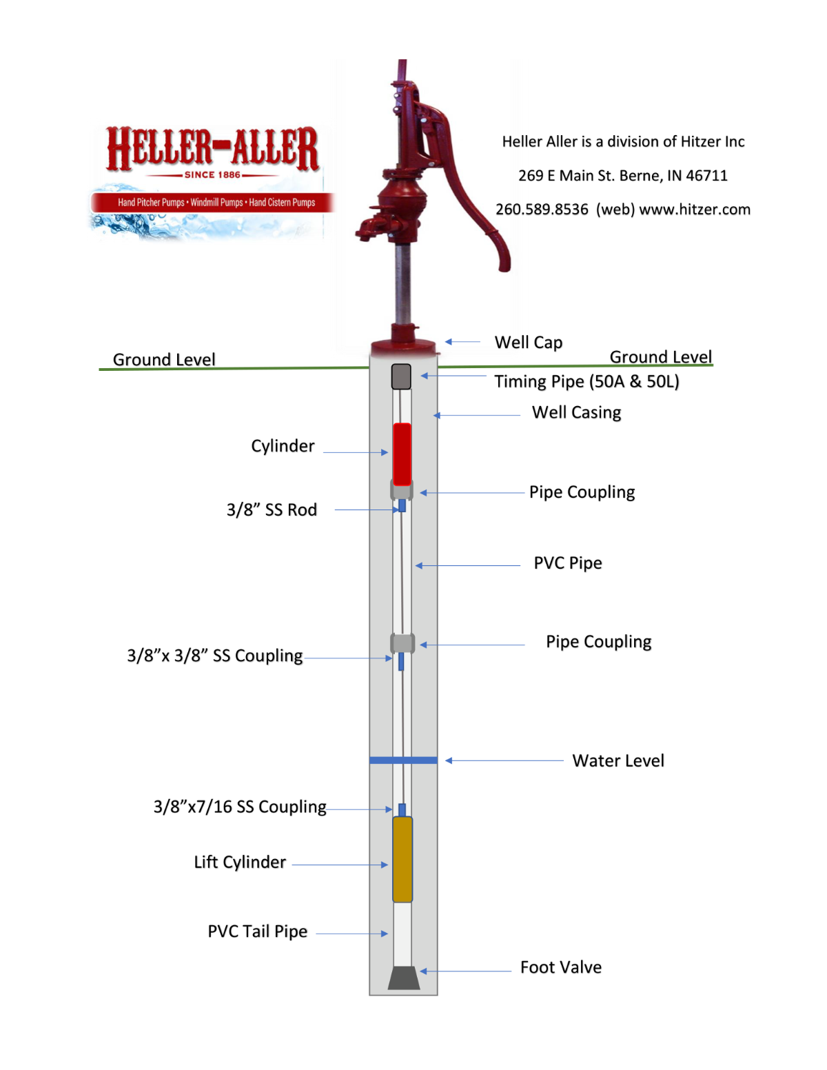
Heller Aller 50L Installation Diagram